Introduction
I thought it would be fun to make a 100W led flashlight like DIYPerks or CNlohr have made previously. I figured this would be a good opportunity to practice making 3D models as well as practice on making multi part prints on my 3D printer (Printrbot Simple Metal). This versions electronics is largely (if not entirely copied) from the DIYPerks video which you should check out for more of a step by step tutorial. One of the main focuses of this was to make a nice 3D printed case around his design.
For those not familiar, there are 100W LEDs on ebay and Aliexpress that are about $3-4 a piece which makes this project a (supposedly) cheap and super bright flashlight. Now this thing won’t be waterproof or rugged like commercially available high brightness LED flashlights, but it is a fun project to do! Here’s the overview of what I will be using:
- 3D printed case
- Large R/C LiPo battery for power
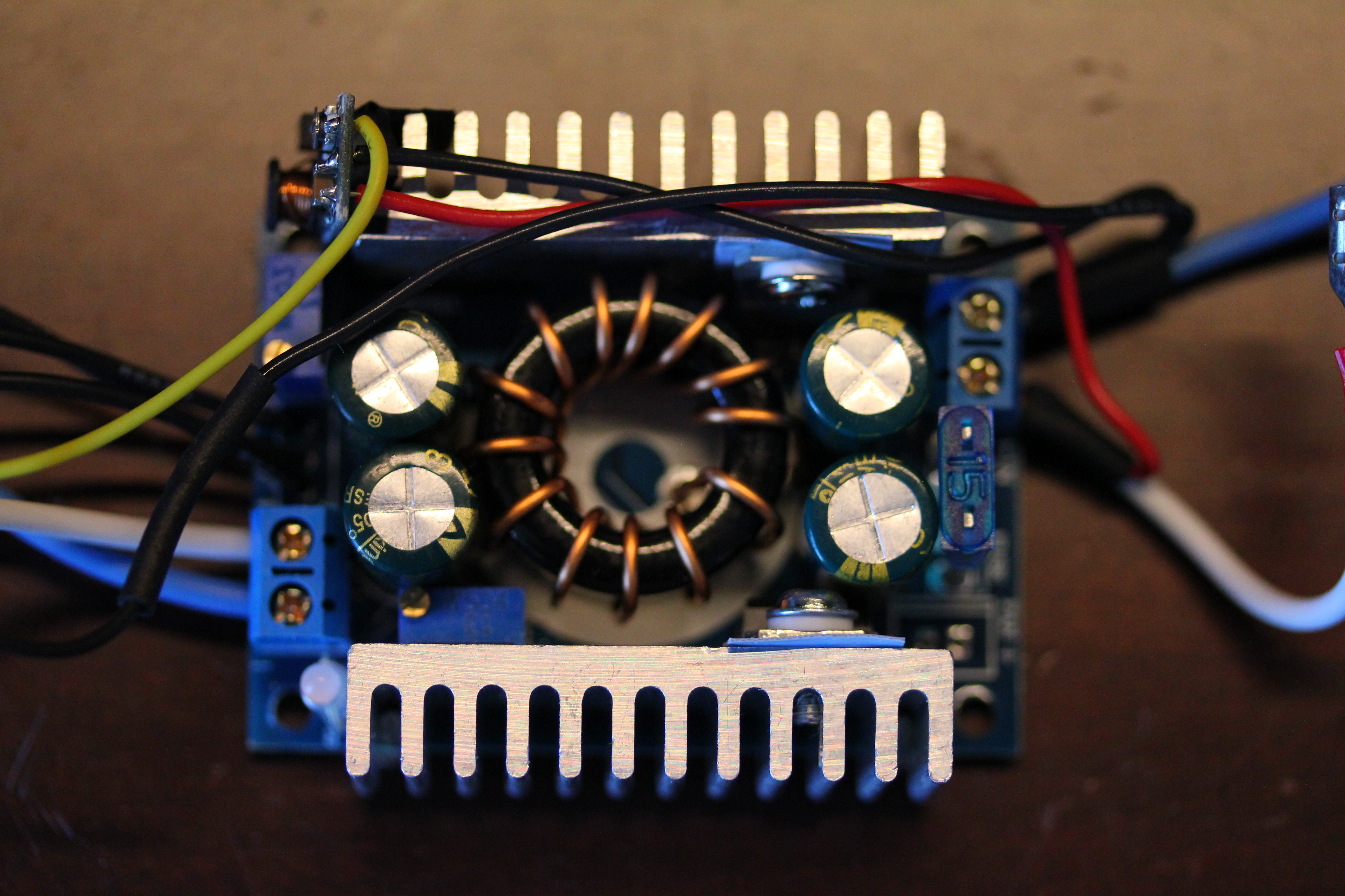
- Constant current boost converter
- 100W LED
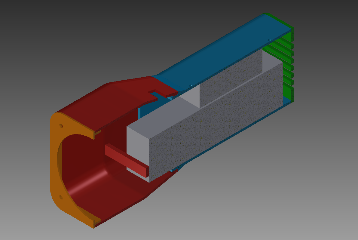
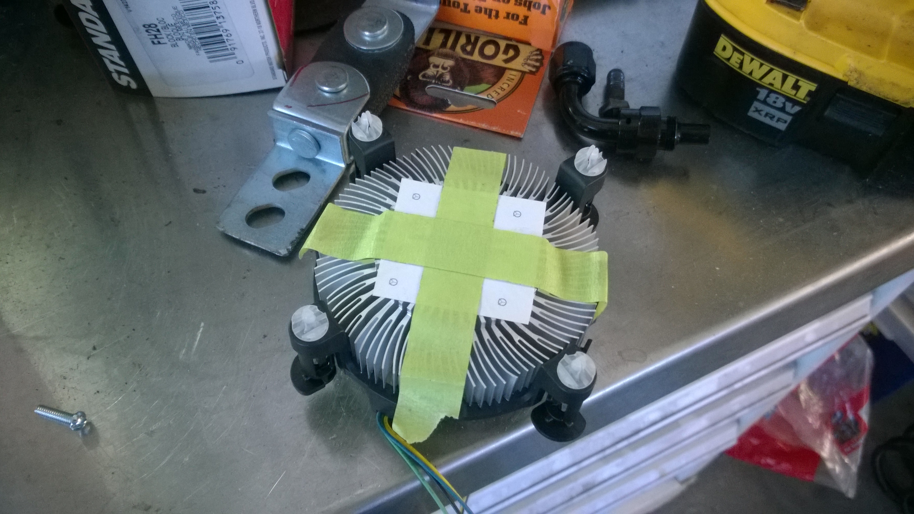
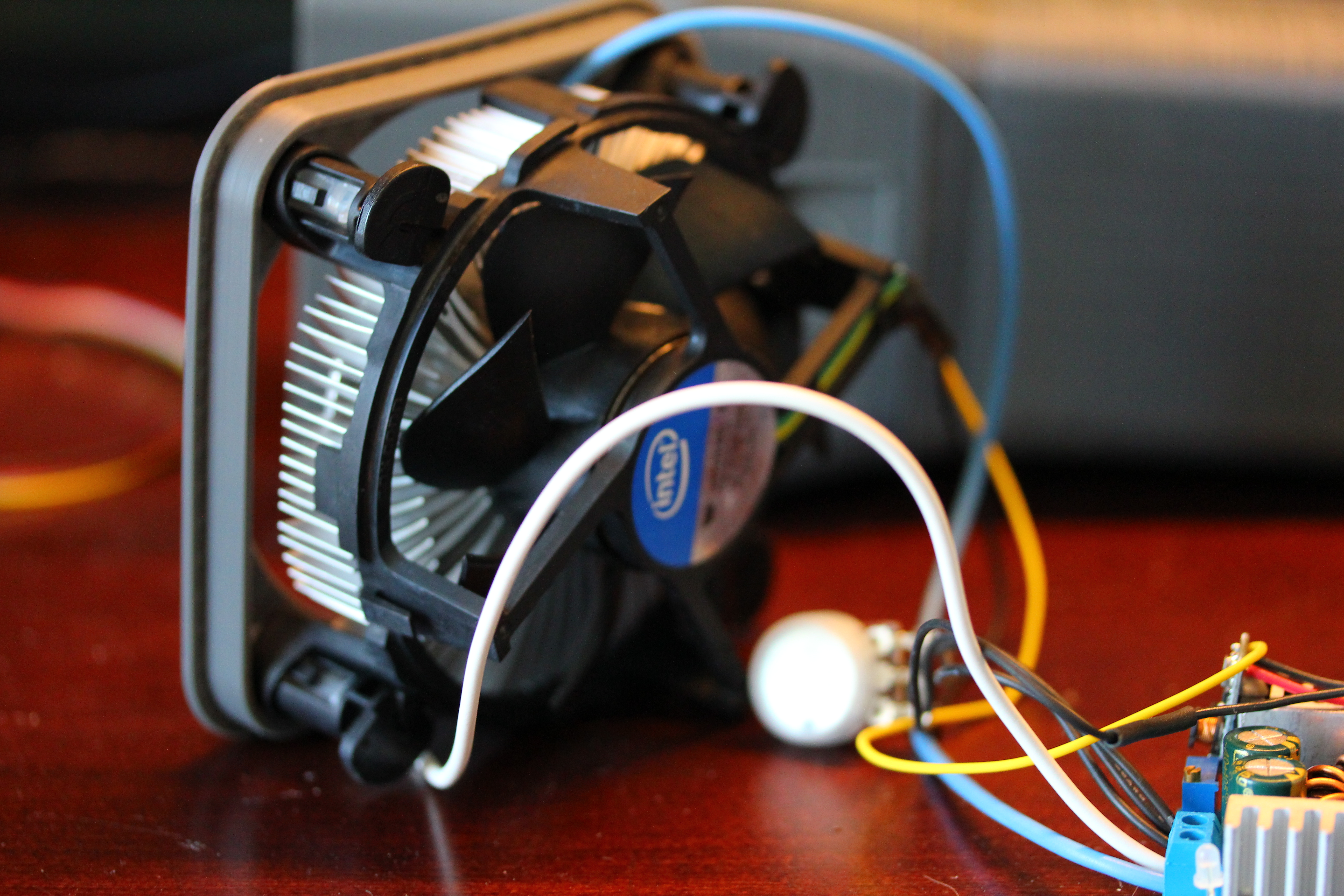
- Stock Intel CPU heatsink to keep things cool
Case Design and Construction
This is the most advanced thing I have ever 3D modeled and during the process I got frustrated with a few things trying to get it to look how I wanted, but eventually everything got done.
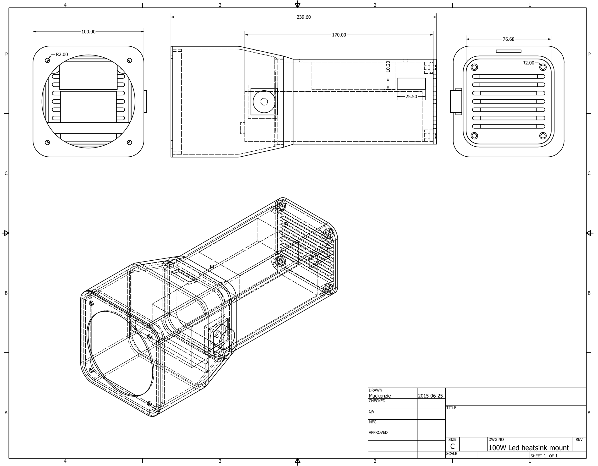
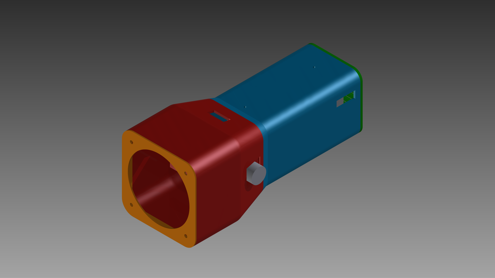
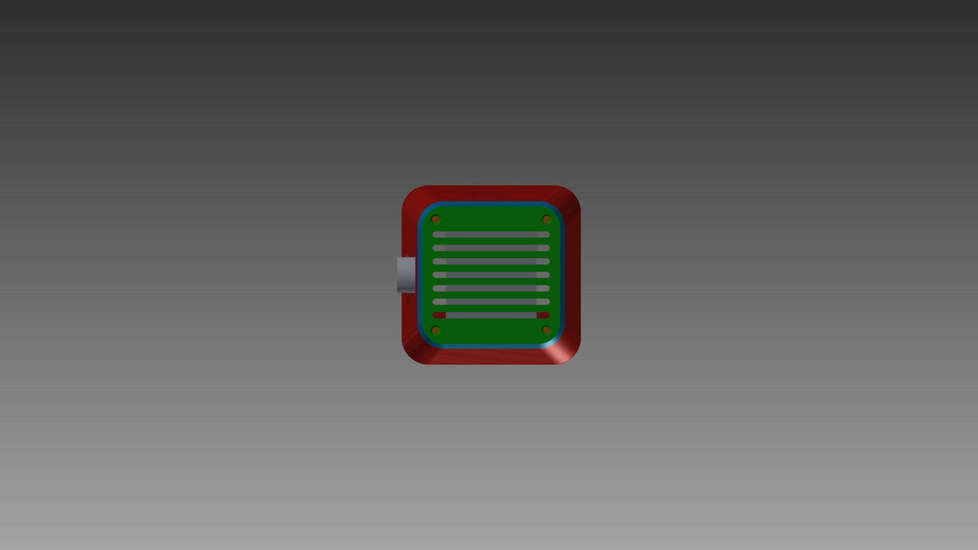
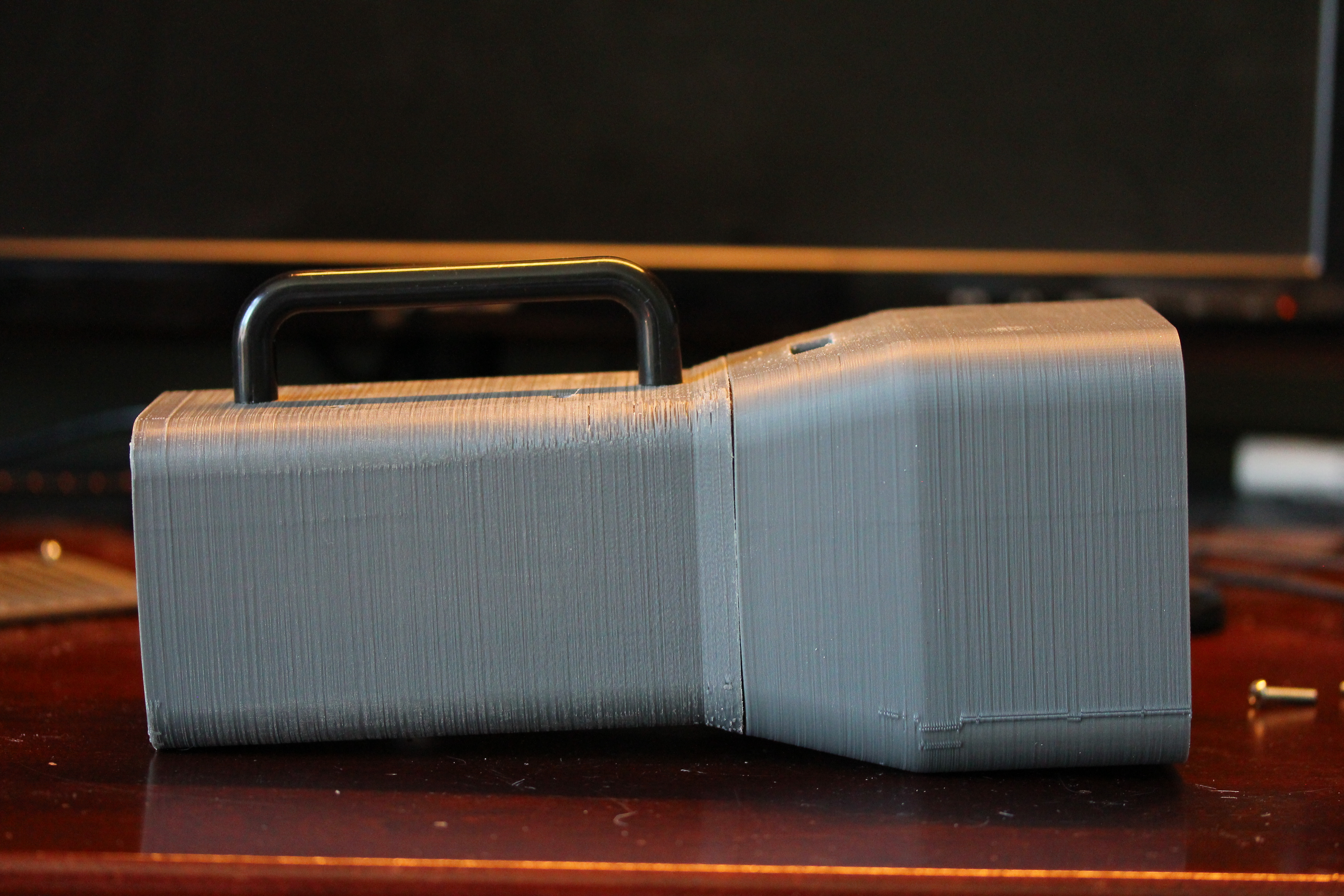
The design of the case is based around three things: the Intel heatsink, the R/C battery, and the boost converter. The front plate was designed so that it was the same as a motherboard so that the heatsink would mount with its original method. The plate is around 1.6mm thick for the pegs of the heatsink to engage. If you don’t have access to a 3D printer then some 1/16″ aluminum should be the correct thickness. The front panel is currently just press fit into the main (bell?) housing so that I can open it up and take the electronics out if need be. Glue could be added to make it stronger but right now if fits snugly. The wider part of the ‘bell’ is how far the heatsink is recessed into it with the gradual slope allowing the battery to slide up into the bell a little bit to shorten the length of the flashlight and give it a nice flashlight look. Also in the bell is the cutout for the battery voltage alarm, and the mount for the potentiometer that controls the brightness.
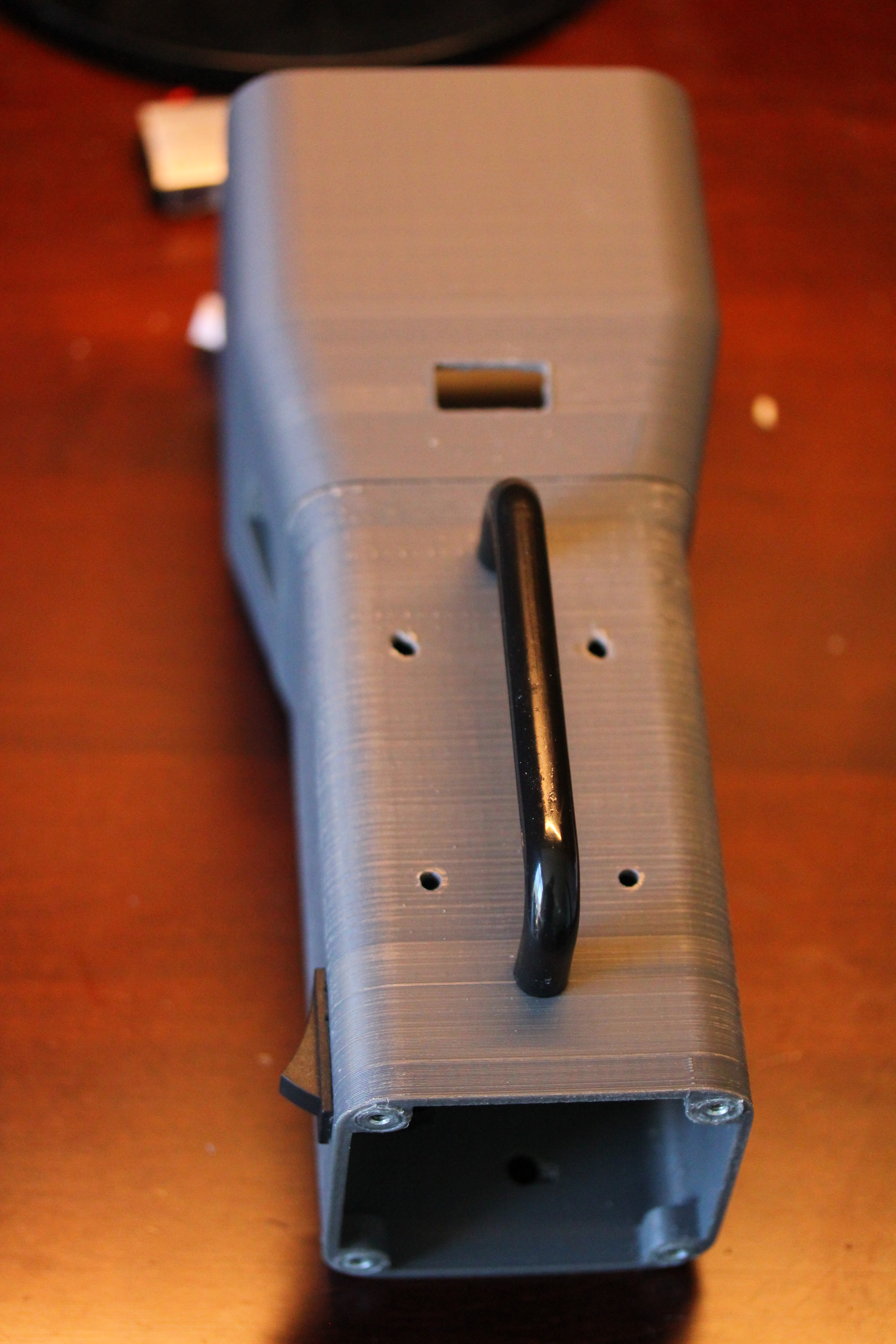
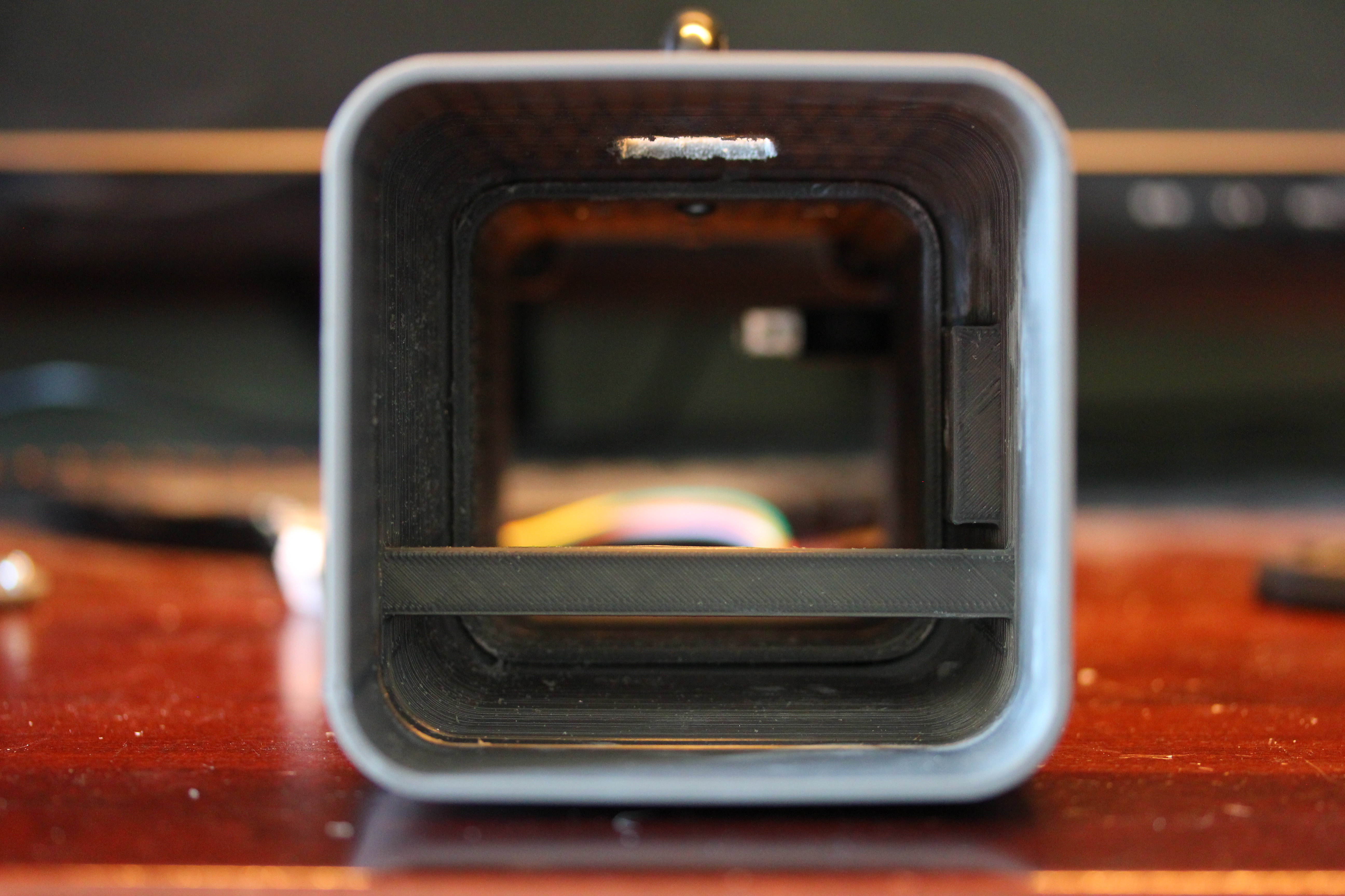
The next part I call the battery compartment since the battery takes up most of its space. Most of the electronics are also mounted in this piece. Again this part is press fit, albeit a little too tightly so I had to do a lot of sanding to get it to insert into the bell. The inside lip of this piece sticks out a bit inside the bell giving a nice sort of lip for me to put glue in. This piece was glued in to make it stronger with a little bit of super glue. The battery compartment houses the carrying handle, on switch, and screw mounts for the back cover. All of the holes in the final print had to be enlarged slightly so things fit correctly, so I need to adjust my tolerances I use when designing for my printer (currently 0.2mm).
And finally we have the back cover which is mounted in place with 10-32 nuts and bolts with the bolts being recessed into their holders and glued in with super glue.


Total print time was somewhere in the neighbourhood of 13 hours for all 4 parts.


Electronics
Most of the electronics are off the shelf parts I ordered from China, either through eBay or Aliexpress.
The LED

This is a 100W (~30ish Volts, 3-3.3A) LED. It has 10 individual LEDs in series which is then put in parallel with 9 other strings to give us a total of 100 dies. From what I’ve seen online it is usually a bad idea to run LEDs in parallel like this due to the fact that if one of the strings gets blown or fails then more current will flow through the other strings causing a cascading failure. Also the fact that LEDs forward voltage can vary from part to part it could cause an imbalance. I believe the way the manufactures of these LEDs get around this is to ‘match’ the LEDs so that each string carries the same current minimizing the risk. I mentioned earlier that these chips are very cheap from China, around $4, when some from Digikey cost about $30. I think this is probably because these are the chips that are rejected due to poor performance during QC. Here is a video by bigclive talking about this.
I got fairly lucky with this chip I used for the light with probably something like 85+% of the LEDs working fine. I also ordered a warm white version from the same seller which was a bit worse unfortunately. Can’t really complain though for $4 with free shipping!
Driving the LED
The LED needs about 30V and 3A to operate which is easy to get if you use an AC adapter from someone like Meanwell. Since we are trying to make this portable though we will copy DIYPerks and just use a large RC battery. This battery is fed through a 150W constant current boost converter which is also from China. The boost converter had a similar modification as in the DIYPerks video where I removed the constant current potentiometer and soldered another one on that I could mount to the side of the case. I went for the more expensive constant current boost converter because I was worried about the thermal runaway if the LED got too hot and started drawing more current. The LED is connected with 18 gauge wire.
Driving the Fan
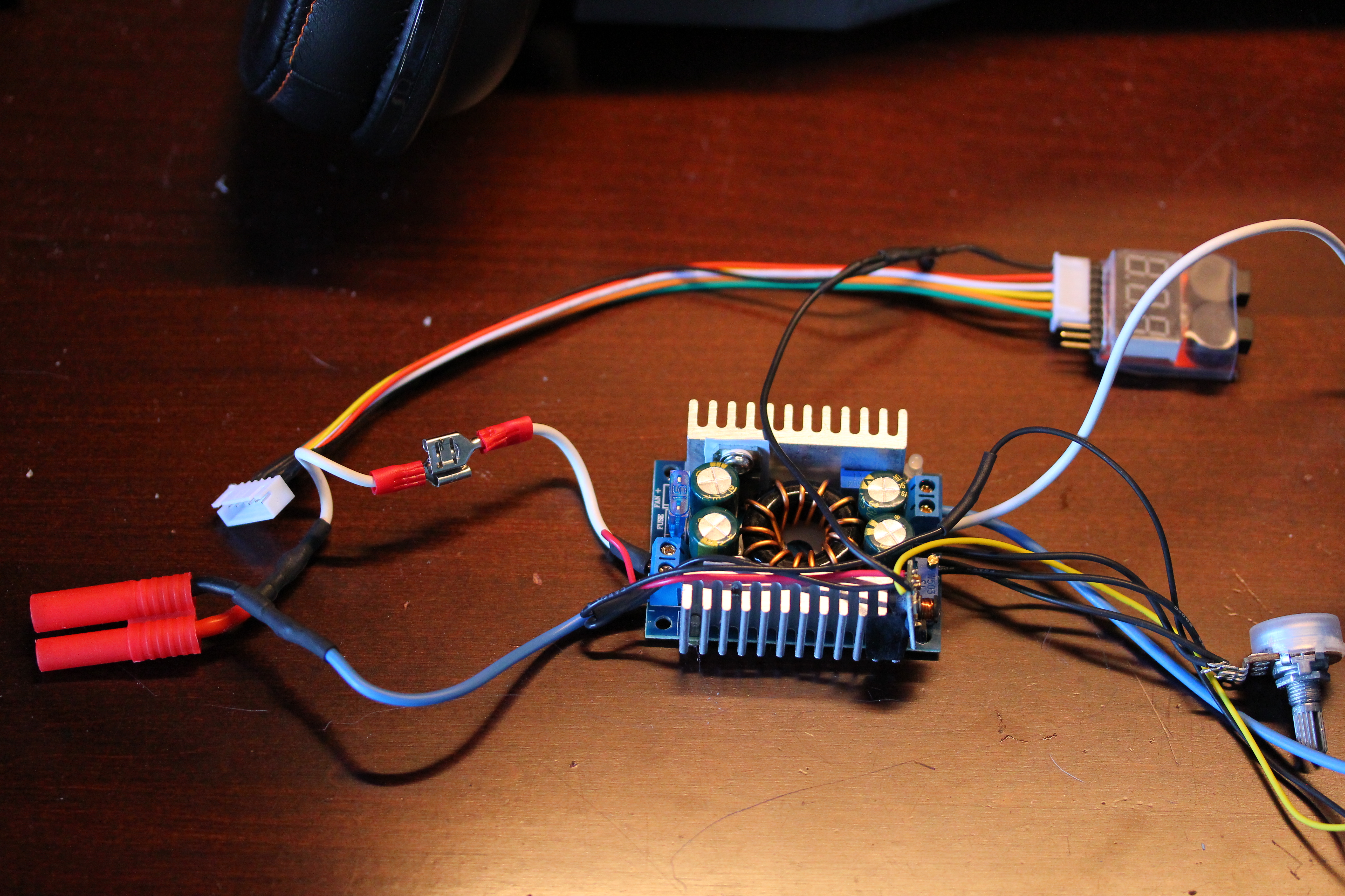
The fan circuit again takes inspiration from DIYPerks using a small DC/DC buck converter to step down the battery voltage to 12V. This board is glued to the heatsink of the boost converter and insulated from it with some electrical tape. This buck converter also drives a transistor that toggles the ground pin of the battery voltage alarm board to turn it on when the main switch is flipped.
The switch is connected to the positive terminal of the battery, hence the need for the transistor.
Battery Voltage Alarm
Also the same part as DIYPerks. It is just a simple board with a couple buzzers, warning LED, and 7 segment display. The balance lead from the battery is connected to an extension cable which is then connected to the alarm board. When any of the cells in the battery gets below 3.2V an audible alarm sounds letting me know the battery is getting low.


Finished!


BOM
Conclusion
A fun project but turned out to be a little more expensive than I was hoping. It’s actually really useful to use as a floodlight, I used it a bit when we were working on our retaining wall at night and it lit everything up nicely. I did get some lenses but haven’t figured out how to mount them yet or if I will even use them since the main advantage this has over a normal flashlight is it being a flood that lights everything up nice and bright.

Hi… Good job! Do you have any desire to share stl files?
Huh, forgot to post the files when I made this post. Just posted them on thingiverse: http://www.thingiverse.com/thing:2182349
а lot of thanks !!!!
Great! nice post!
How cool does the LED run? can you leave it on for extended periods of time?
I usually run it for a decently long time, although I don’t always run it at full power. If I made it again, I would run the fan much faster to get more airflow, and cut some holes in the bell to get more ventilation. I also had my batteries start to bulge on me, so not sure if that was from heat, over discharge or what. Something to keep in mind. Probably want to disconnect battery when not in use (including balance leads).
Ok cool. What infill did you use because I went to print the heat sink compartment and it said it would take 14 hours and you put on the post that it took you about 13 hours for everything?
Would you recommend leaving the battery alarm plugged all the time.
Hi, why use 5s lipo? Is there any advantage over using 3s ?
LED Flashlight is the best ever app i have ever use…I love it..
https://play.google.com/store/apps/details?id=com.zonalapps.ledflashlight.torchlight